|
Network tagged blogs
| DoS Attacks |  |
|---|
|
-14th of November 2009
This piece of text will summarize some DoS attacks. There propably new invented all the time, so this is not an attempt of a full complete list.
Denial of Service Attacks(DoS) are defined easily by the following three lines:
1. Extensive overuse and abuse of resources that leads to downtime and instabillity of services.
2. Physical attacks on infrastructure.
3. Change or destruction of system configuration.
|
*SYN attack: This attack occurs when the attacker floods the victim with TCP SYN packets(the first step in a three way handshake). This opens a TCP session, the victim
replies with a TCP SYN-ACK reply, but gets no reply from the initiator. The source address of the TCP SYN packets are often spoofed, and that is why
the host that receives the TCP SYN-ACK reply does not recognize the session and ignores it. There might not even be a valid source
address in the TCP SYN packet, resulting in the TCP SYN-ACK packet to be dropped somewhere in the network.
When the victim receives a flood if TCP SYN requests, this can result in a buffer overflow. The memory used to store initiated TCP sessions
is overrun before the sessions time out. This results in the victim not being able to answer more TCP request, and therefore
seems unresponsive to other clients. This attack can be prevented in several ways, including shortening timeout intervals for TCP sessions,
incresing the TCP buffer, setting up a firewall to recognize TCP SYN attacks, and installing Intrusion Detection / Intrusion Prevention Systems(IDS/IPS).
*Ping of death: Fragmented ICMP ping packets are sent to the victim, bypassing MTU, overriding the 65 535 byte limit of a ICMP packetand when the fragments are reassembled. This causes a buffer overflow that can result in DoS or other unforseen behaviour.
This attack can be prevented by properly configured firewalls.
*Teardrop: Fragmented IP packets are sent to the victim. As the firewall only checks the first packet in the fragmented
seqence, the following packets will overwrite the destination information and maybe also the source address information. This results in a
completely different receiver of the packet, and maybe also a different source address then the firewall first thought. And thus
bypassing the firewall completely.
|
|
*Smurf Attack: This is a broadcast of ICMP packets with a spoofed source address. The receiver of the ICMP broadcast packets and also the source address receiving the replies will be under a DoS attack through flooding and excessive resource usage.
Prevention against Smurf attacks include blocking of ICMP broadcasts in a firewall.
>More info.
*Fraggle Attack: The same as the Smurf Attack, but then with UDP brodcasts and not ICMP broadcasts. Prevention of UDP broadcast attacks, include blocking of UDP broadcasts in a firewall. Much the same as the Smurf Attack.
*Spoofing: Setting a fake source address on a transmitted package.
>More info.
*Session Hijacking: Take over one side of a communicating session, or both sides.
Session-Hijacking can be done through listening to the communication between two parties and steal the session by
answering a part of the communication with the correct session ID. This results in the host answering to the hijacker,
and dropping the correct client. The correct client will perseve the incident as just a lost connection to the host. Since the
client no longer has the correct session ID(it is incremented in the session), the client can not rejoin the communication automatically.
If the client wants the session back, he would have to hijack it back. Another way to get the session ID, would be to brute force for a session ID(more likely to be detected).
>More info.
*Land.c : The victim receives a packet with the same source address as destination address. The victim will then try to reply to itself, resulting in a loop. This attack can easily be prevented by blocking all packets that have the same source address as destination address.
*Christmastree packets: The victim receives a TCP packet with all the flags set. The response is analyzed for further attacks. Can be prevented by properly configuring firewalls.
*Buffer Overflow: Excessive overrun and flooding of a victims resources, resulting in DoS(Denial Of Service).
*Factory standardized configuration of equipment: Can lead to unauthorized access, resulting in a security breach and possibly DoS.
*E-mail bombs. Excessive sending of e-mail, often as a result of a trojan or a virus. Consequences are DoS of mail or network services.
>More info.
|
Aditionally, other dangers have always been rootkits, phishing, trojans, viruses, and other malware. These can ultimately end in a DoS attack. General
precoutions against DoS or DDoS attacks are installing IDS/IPS systems, make agreements with ISP's for further protection, keep an eye on vulnerabilities,
and keep you system patched and up to date.
Source: Høgskolen i Sør-Trøndelag
Tagged as: Network |
| Local Network Security Actions | |
|---|
|
-16th of September 2009
|
|
1. Make sure the packages leaving your network to the internet are leaving with the same source address as the network it is leaving from. Implement a blocking of all suspicous packages with phony source addresses, to help protect the outside world from possibly owned/infected or taken over computer systems on your network.
2. Block incomming packages from the internet that are addressed to broadcast addresses on the internal network. There is no reason why external clients or devices should be allowed to broadcast on your internal network.
3. Turn off the Direct Broadcast capability of your internet router, unless it is absolutely essential. This will hinder potential attackers from the outside to broadcast various types of attacks into your network. See for instance the blog on DoS attacks for some examples.
4. Block all packages arriving from the internet that have source addresses that are within the non-routable spectre defined by RFC1918. These are 10.0.0.0/8, 172.16.0.0/12 and 192.168.0.0/16. These addresses are set by RFC1918 to be private and non-routable on the internet. Routers on the internet will drop these by default. If you receive packages from the internet with source addresses in these address spaces, it should be seen as suspicious activity.
|
Source: Computer Security Handbook, 5th Edition. ISBN: 978-0-470-32722-7
Tagged as: Network |
| Linux Firewalls | |
|---|
-13th of January 2013
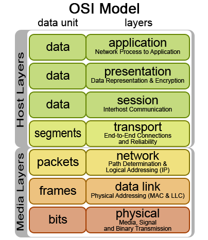
When evaluating a network packet, the firewall will read header information in the packet for the corresponding layer in the OSI Model
to evaluate this against the rules in a iptables chain. The iptables firewall is capable of handeling network information from all of the network layers, however it is not initially designed to do so. In the examples
that will be given below, there will be explained usage of the iptables firewall in conjunction with MAC addresses(Data Link layer), IP addresses(Network layer), and TCP/UDP ports(Transport layer).
When sending information over the network, the information is divided into packages that get encapsulated into protocols in the different layers of the OSI model. The packages are always divided into a size
specified by the Maximum Transmission Unit(MTU) of the sending interface. Typically this size is 1500 bytes, but can be up to 9000 bytes and then called Jumbo Frames.
If the package encounters equipment with a lower MTU than it was originally handeled by, the package will be further divided. Small packages create more protocol overhead but require less data to be re-transmitted if the package is lost.
Thus a small MTU is preferable for a network that is in some sort less reliable. A large MTU requires less overhead and thus more information can be transmitted faster. A large MTU is a good choice for networks that experience low
retransmissions and are considered fairly reliable.
This protocol overhead that is added to the packages that are to be transmitted has various information essential for the receiving part, or essential for the equipment used to send the package on its way to the destination.
This packet to be transferred typically starts its life at the application layer and traverses downwards to the physical layer where it is sent over the medium used for networking.
A series of packages typically make up a whole piece of information that is to be received by the receiver, and is put together at the receiving end. When transmitting information with the IP protocol,
it is possible to encapsulate it/transmit it over the TCP or UDP protocols on the Transport layer. Each of these represent two different transport mechanisms. TCP establishes a session
with a three-way-handshake and ensures that all packages belonging to
that session are tagged with sequence numbers and transmitted correctly over the wire. If packages are lost or mangled in the transport process, they are re-requested and re-transmitted.
TCP also ensures that the receiver can put the packages together in the correct order. TCP does however have a higher overhead then UDP, wich is a stateless protocol.
With UDP no attempt is made to establish a session, the packages are just put on the wire with a destination address hoping that the receiver will receive them and have
the necessary applications to handle and interpret the information received. This method of package transmission demands less overhead and is a good choice for realtime
communication that needs to arrive at its target fast, but not necessarily in the correct order or at all. Many popular network enhanced games use the UDP protocol when communicating
over the network.
| |
The Linux iptables firewall consists of a set of chains with firewall rules that a network packet gets evaluated by in the order that the chains are set up.
As illustrated on the picture to the right, a packet will traverse the PREROUTING chain before it is sent to either the INPUT chain or the FORWARD chain depending on if the packet is intended for this
particular host, or if it needs to be forwarded to another network that the receiving host is connected to.
To forward network traffic to other networks, the host needs to be configured as a router.
Examples of iptable rules set by a script or via the terminal:
1. iptables -A INPUT -p icmp -m icmp -m limit --limit 2/second -j ACCEPT
2. iptables -A INPUT -i lo -s 127.0.0.1 -j ACCEPT
3. iptables -A INPUT -m mac --mac-source 00:20:b0:4b:6f:1b -j ACCEPT
4. iptables -A INPUT -p tcp -i eth1 --dport 21 -j ACCEPT
5. iptables -A INPUT -p tcp -i eth1 --dport 20 -j ACCEPT
6. iptables -A INPUT -m state --state RELATED,ESTABLISHED -j ACCEPT
7. iptables -A INPUT -m state --state INVALID -j DROP
8. iptables -A INPUT -p tcp ! --syn -m state --state NEW -j DROP
9. iptables -A INPUT -p tcp --tcp-flags ALL ALL -j DROP
10. iptables -A INPUT -p tcp --tcp-flags ALL NONE -j DROP
11. iptables -A INPUT -p icmp -m icmp --icmp-type address-mask-request -j DROP
12. iptables -A INPUT -p icmp -m icmp --icmp-type timestamp-request -j DROP
|
Explanation to the rules listed above:
1. Limit the amount of ping packets(icmp) to the input chain to two per second, to avoid icmp flood attacks/DOS attack.
2. Allow the loopback interface to communicate with the host. This is often required by several applications that might be running on the host.
3. Allow sender with a specified mac source address to pass the INPUT chain. Note that mac addresses can be spoofed.
4. Allow packets over the INPUT chain arriving at TCP port 21 to pass. Often required by FTP servers.
5. Allow packets over the INPUT chain arriving at TCP port 20 to pass. Often required by FTP clients in active mode.
6. Allow packets over the INPUT chain that are a part of a related or already established communication transaction.
7. Drop packets that are considered invalid.
8. If a packet is considered new and not a part of a already established TCP session, and the syn flag is not set, then drop it.
9. If a packet has all the TCP flags set, it is considered invalid and dropped. TCP packets with all the flags set are suspected to be Christmastree packets.
10. If no TCP flags are set on the TCP packet, it is considered invalid and dropped.
11. ICMP(ping) packets that request address mask information are dropped.
12. ICMP(ping) packets that request timestamp information are dropped.
|
More information regarding various iptables rules that can be applied to iptable chains can be found at various sites on the internet and is recommended reading.
| |
The Linux iptables firewall is often used together with technologies like Snort, FWSnort and PSAD.
Snort is generally used to monitor and log network traffic to alone form a Intrusion Detection System(IDS).
However, when PSAD and FWSnort, or Snort is used together in conjunction with iptables, it forms an Intrusion Prevension System(IPS).
A graphical interface to these systems can be set up with several GUI systems, like BASE or OSSIM.
Better yet, the commandline interface that the iptables firewall has, makes it easily scriptable and thus tweakable through various script languages(e.g. Perl, BASH, Python).
Iptables with its capabillities reaching alot further then mentioned here therefore gets to be a nerds dream in a tweakable Linux world.
Sources: Linux Firewalls. ISBN: 978-1-59327-141-1
Drift av lokalnettverk. ISBN: 82-519-2075-2
Tagged as: Linux, Network |
| Netmap, Netcat, Nmap, Netstat and TCPDump | |
|---|
-20th of December 2013
NETCAT
Netcat as a server to setup port for testing a network connection:
nc -w 600 -k -l 2389
Netcat will listen for 600 seconds(-w) and then stay up after the client disconnects(-k). The client will listen on port 2389.
To test the connection to the netcat server, you can use telnet from a different machine on the same network:
telnet -e p 192.168.1.102 2389
press p
type quit
press enter
We can also test the connection with netcat as a client:
nc 192.168.1.102 2389
Send a file over with netcat using udp(-u):
>at the server: $ nc -u -l 2389 > outputfile
>at the client: cat testfile | nc -u localhost 2389
Netcat as a client via a gateway and spoofing its IP:
nc -s spoofed_ip -g <gateway> remote_host <port>
Note: Up to eight hop points may be specified using the -g flag.
Netcat as a port scanner:
nc -r -w1 -v -n -z 192.168.1.108 3305 – 3320
-r for random ports in range
-w1 for wait 1 second for a reply
-v for verbose output
-n for no name resolution
-z for send no data
Get all header replies from services listening on ports in range:
echo "" | nc -v -n -w1 192.168.1.108 3306 – 3307
Example reply: Host 'router.net.local' is not allowed to connect to this MySQL server
Netcat proxy to Google that sends responses on port 123456 back to client:
nc -l -p 12345 | nc www.google.com 80 | nc -l -p 12346
Show a web page on port 80:
while true; do nc -l -p 80 -q 1 < error.html; done
Send a partition over the network with netcat:
Receiving side:
nc -l -p 9000 | dd of=/dev/sda
Sending side:
dd if=/dev/sda | nc 192.168.0.1 9000
|
NMAP
NBTSCAN
NBTSCAN is the Linux version of NBTSTAT, and can handle ranges of addresses instead of just a single host.
nbtscan -hv 192.168.1.0/24
The tool will scan for netbios information on the host.
nbtscan 192.168.1.0/24
More NBTSCAN examples
NETSTAT
|
Source: Manual pages
Tagged as: Linux, Commands, Network |
| Deep Security Virtual Patching | |
|---|
|
-29th of June 2013
Virtual Patching
In Deep Security IPS is what makes up Virtual Patching.
See page 74 in the Deep Security Administration guide. DPI will inspect the traffic to the guest system and use IPS to block any
traffic that might be exploiting known vulnerabilities that are fixed in patches not yet applied to the guest system.
1. In the Deep Security Console, go to computers.
2. Choose a test machine and double click it.
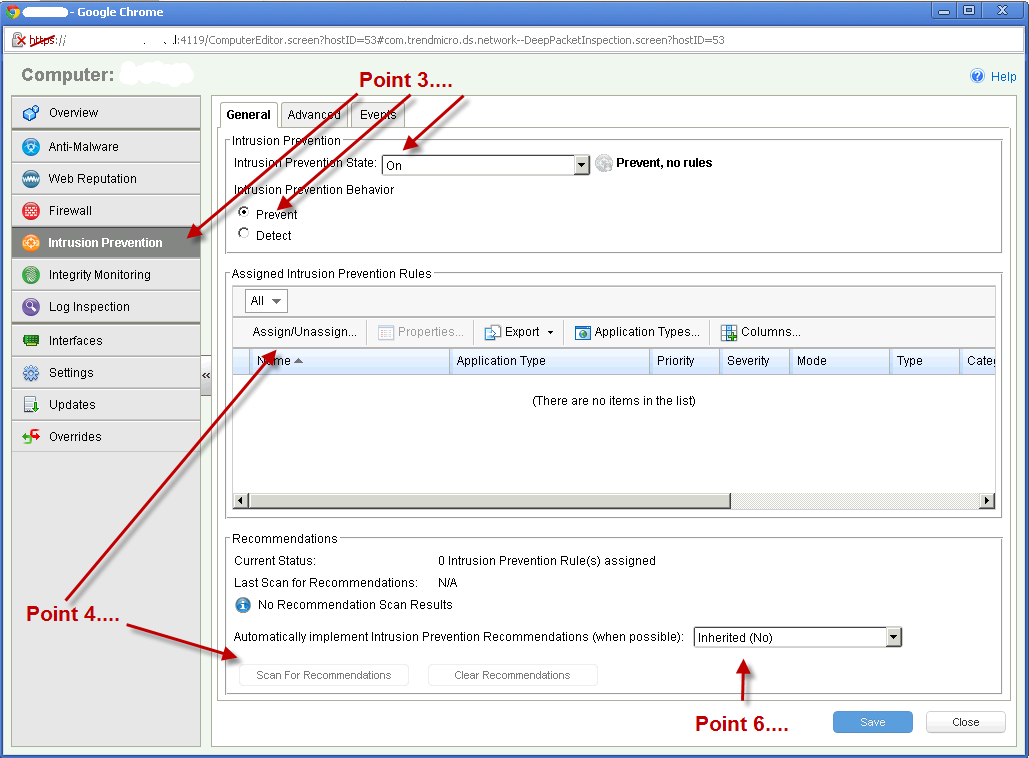
3. Choose 'Intrusion prevention' and choose ON, then decide if you want 'Detect' or 'Prevent'.
4. Choose to add rules manually (Assign/Unassign button) or choose to get recommendations (then press the button 'Scan for Recommendataions').
5. If you choose the manual method, then just check off the rules you want and right click so that you can choose 'Assign rules -> to all interfaces'
6. If you choose 'Scan for Recommendations' you can either choose to let the rules automatically be added or see what is recommended.
7. Usually it is adviceable to choose under Assign/Unassign -> 'Recommended for assignment.'
8. Then right click 'select all' - right click and 'Assign rules -> to all interfaces.'
Please see the illustration on the right.
For further information, please see the administration manual.
|
|
Source: Deep Security 9 Administration Manual
Tagged as: VMWare, HowTo, Network |
| OpenVPN server on RaspberryPI 1 vs RaspberryPI 3 | |
|---|
-1st of November 2017
This article will briefly describe an experiment with performance on a Open VPN server running on Raspberry PI 1 vs running on Raspberry PI 3. Both hardware units are running Raspbian as the operating system.
Note: D:\ represents the command prompt and is not actually a part of the commands shown below.
Before we start the following needs to be summarized:
- The available download speed as seen from the OpenVPN router is 80 Mbps
- The available upload speed as seen from the OpenVPN router is 30 Mbps
- How to set up a OpenVPN server will not be described here.
- The OpenVPN server / client is not set up to compress and decompress traffic as this will load the CPU on the OpenVPN server more than I trust it to.
- There is only one client at a time in this scenario.
There are essentially two OpenVPN servers set up, one one RaspeberryPI 1 and one on RaspberryPI 3. They both route to the same network where the same
Windows 10 machine is running a server instance of iperf3. It can be started like so:
iperf3.exe -s
After the Iperf3 server process is startet at the Windows 10 machine, I will connect to the network remotely from a remote location in a neighboring city via OpenVPN, first using the Raspberry PI 1 based Open VPN router, then using the Raspberry PI 3 based Open VPN router.
Each time I run iperf3 as a client from my VPN klient, connecting to the iperf3 server through the given OpenVPN server at the time and measuring the network throughput I get.
So, lets start by connecting through Raspberry PI 1 first, then Raspberry PI 3.
|
Speeds as seen through OpenVPN via Raspberry PI 1.
          Microsoft Windows [Version 6.1.7601]
          Copyright (c) 2009 Microsoft Corporation.  All rights reserved.

          D:\Users\User\Downloads\iperf-3.1.3-win64>iperf3.exe -c 192.168.100.51 -t 10
          Connecting to host 192.168.100.51, port 5201
          [  4] local 172.16.11.123 port 28041 connected to 192.168.100.51 port 5201
          [ ID] Interval           Transfer     Bandwidth
          [  4]   0.00-1.00   sec  1.00 MBytes  8.39 Mbits/sec
          [  4]   1.00-2.00   sec   896 KBytes  7.34 Mbits/sec
          [  4]   2.00-3.00   sec   896 KBytes  7.34 Mbits/sec
          [  4]   3.00-4.00   sec   896 KBytes  7.34 Mbits/sec
          [  4]   4.00-5.00   sec   896 KBytes  7.34 Mbits/sec
          [  4]   5.00-6.00   sec   896 KBytes  7.34 Mbits/sec
          [  4]   6.00-7.00   sec   768 KBytes  6.29 Mbits/sec
          [  4]   7.00-8.00   sec   896 KBytes  7.34 Mbits/sec
          [  4]   8.00-9.00   sec  1.00 MBytes  8.39 Mbits/sec
          [  4]   9.00-10.00  sec   768 KBytes  6.29 Mbits/sec
          - - - - - - - - - - - - - - - - - - - - - - - - -
          [ ID] Interval           Transfer     Bandwidth
          [  4]   0.00-10.00  sec  8.75 MBytes  7.34 Mbits/sec                  sender
          [  4]   0.00-10.00  sec  8.66 MBytes  7.26 Mbits/sec                  receiver

          iperf Done.

          D:\Users\User\Downloads\iperf-3.1.3-win64>iperf3.exe -c 192.168.100.51 -t 10
          Connecting to host 192.168.100.51, port 5201
          [  4] local 172.16.11.123 port 1041 connected to 192.168.100.51 port 5201
          [ ID] Interval           Transfer     Bandwidth
          [  4]   0.00-1.00   sec  1.00 MBytes  8.39 Mbits/sec
          [  4]   1.00-2.00   sec  1.00 MBytes  8.38 Mbits/sec
          [  4]   2.00-3.00   sec   896 KBytes  7.35 Mbits/sec
          [  4]   3.00-4.00   sec   896 KBytes  7.34 Mbits/sec
          [  4]   4.00-5.00   sec  1.00 MBytes  8.39 Mbits/sec
          [  4]   5.00-6.00   sec  1.00 MBytes  8.39 Mbits/sec
          [  4]   6.00-7.00   sec   896 KBytes  7.34 Mbits/sec
          [  4]   7.00-8.00   sec  1.00 MBytes  8.39 Mbits/sec
          [  4]   8.00-9.00   sec  1.00 MBytes  8.39 Mbits/sec
          [  4]   9.00-10.00  sec   896 KBytes  7.34 Mbits/sec
          - - - - - - - - - - - - - - - - - - - - - - - - -
          [ ID] Interval           Transfer     Bandwidth
          [  4]   0.00-10.00  sec  9.50 MBytes  7.97 Mbits/sec                  sender
          [  4]   0.00-10.00  sec  9.41 MBytes  7.89 Mbits/sec                  receiver

          iperf Done.
|
Speeds as seen through OpenVPN via Raspberry PI 3.
          D:\Users\User\Downloads\iperf-3.1.3-win64>iperf3.exe -c 192.168.100.51 -t 10
          Connecting to host 192.168.100.51, port 5201
          [  4] local 172.16.11.123 port 1080 connected to 192.168.100.51 port 5201
          [ ID] Interval           Transfer     Bandwidth
          [  4]   0.00-1.00   sec  2.00 MBytes  16.8 Mbits/sec
          [  4]   1.00-2.00   sec  3.75 MBytes  31.5 Mbits/sec
          [  4]   2.00-3.00   sec  3.88 MBytes  32.5 Mbits/sec
          [  4]   3.00-4.00   sec  3.75 MBytes  31.5 Mbits/sec
          [  4]   4.00-5.00   sec  4.00 MBytes  33.6 Mbits/sec
          [  4]   5.00-6.00   sec  2.75 MBytes  23.1 Mbits/sec
          [  4]   6.00-7.00   sec  2.50 MBytes  21.0 Mbits/sec
          [  4]   7.00-8.00   sec  3.38 MBytes  28.3 Mbits/sec
          [  4]   8.00-9.00   sec  4.00 MBytes  33.6 Mbits/sec
          [  4]   9.00-10.00  sec  3.88 MBytes  32.5 Mbits/sec
          - - - - - - - - - - - - - - - - - - - - - - - - -
          [ ID] Interval           Transfer     Bandwidth
          [  4]   0.00-10.00  sec  33.9 MBytes  28.4 Mbits/sec                  sender
          [  4]   0.00-10.00  sec  33.8 MBytes  28.3 Mbits/sec                  receiver

          iperf Done.

          D:\Users\User\Downloads\iperf-3.1.3-win64>iperf3.exe -c 192.168.100.51 -t 10
          Connecting to host 192.168.100.51, port 5201
          [  4] local 172.16.11.123 port 1099 connected to 192.168.100.51 port 5201
          [ ID] Interval           Transfer     Bandwidth
          [  4]   0.00-1.00   sec  4.00 MBytes  33.6 Mbits/sec
          [  4]   1.00-2.00   sec  2.00 MBytes  16.8 Mbits/sec
          [  4]   2.00-3.00   sec  4.00 MBytes  33.6 Mbits/sec
          [  4]   3.00-4.00   sec  3.88 MBytes  32.5 Mbits/sec
          [  4]   4.00-5.00   sec  3.88 MBytes  32.5 Mbits/sec
          [  4]   5.00-6.00   sec  3.38 MBytes  28.3 Mbits/sec
          [  4]   6.00-7.00   sec  3.00 MBytes  25.2 Mbits/sec
          [  4]   7.00-8.00   sec  3.62 MBytes  30.4 Mbits/sec
          [  4]   8.00-9.00   sec  4.12 MBytes  34.6 Mbits/sec
          [  4]   9.00-10.00  sec  4.38 MBytes  36.7 Mbits/sec
          - - - - - - - - - - - - - - - - - - - - - - - - -
          [ ID] Interval           Transfer     Bandwidth
          [  4]   0.00-10.00  sec  36.2 MBytes  30.4 Mbits/sec                  sender
          [  4]   0.00-10.00  sec  36.2 MBytes  30.3 Mbits/sec                  receiver

          iperf Done.
|
Summary:
we can see, the Raspberry PI 3 offers much better speeds for a OpenVPN server.
Sources: None
Tagged as: Linux, Routers, Network |
|